In my last post, we walked through setup of an ESP8266 project managed with UV. Now we’ll construct a more complex project, adding a simple OLED display.
Hardware
Parts needed:
- esp8266 board
- OLED 0.96 inch Display
- jumper wires
- breadboard
(All of this is included in the ESP32 Basic Starter Kit).
Follow this schematic:
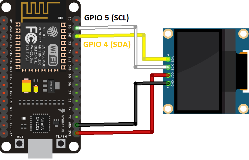
Connections:
| OLED | ESP8266 |
|---|---|
| VCC | 3.3V |
| GND | GND |
| SCL | GPIO 5 (D1) |
| SDA | GPIO 4 (D2) |
Software
Initialize Project
mkdir esp8266_oled

cd esp8266_oled

uv init
Add Dependencies
uv add esptool

uv add adafruit-ampy
Make sure you can communicate with the esp8266:
uv tool run --from esptool esptool.py chip_idFlash MicroPython to the ESP8266
wget https://micropython.org/resources/firmware/ESP8266_GENERIC-20241129-v1.24.1.bin

uv tool run --from esptool esptool.py erase_flash

uv tool run --from esptool esptool.py --baud 460800 write_flash --flash_size=detect 0 ESP8266_GENERIC-20241129-v1.24.1.bin
Create Scripts
The MicroPython standard library doesn’t include support for the OLED by default. We’ll create a new ssd1306.py file and update it with the required code.
touch ssd1306.pyCopy the contents of https://github.com/RuiSantosdotme/ESP-MicroPython/raw/master/code/Others/OLED/ssd1306.py into the file:
# MicroPython SSD1306 OLED driver, I2C and SPI interfaces created by Adafruit

import time
import framebuf

# register definitions
SET_CONTRAST        = const(0x81)
SET_ENTIRE_ON       = const(0xa4)
SET_NORM_INV        = const(0xa6)
SET_DISP            = const(0xae)
SET_MEM_ADDR        = const(0x20)
SET_COL_ADDR        = const(0x21)
SET_PAGE_ADDR       = const(0x22)
SET_DISP_START_LINE = const(0x40)
SET_SEG_REMAP       = const(0xa0)
SET_MUX_RATIO       = const(0xa8)
SET_COM_OUT_DIR     = const(0xc0)
SET_DISP_OFFSET     = const(0xd3)
SET_COM_PIN_CFG     = const(0xda)
SET_DISP_CLK_DIV    = const(0xd5)
SET_PRECHARGE       = const(0xd9)
SET_VCOM_DESEL      = const(0xdb)
SET_CHARGE_PUMP     = const(0x8d)


class SSD1306:
    def __init__(self, width, height, external_vcc):
        self.width = width
        self.height = height
        self.external_vcc = external_vcc
        self.pages = self.height // 8
        # Note the subclass must initialize self.framebuf to a framebuffer.
        # This is necessary because the underlying data buffer is different
        # between I2C and SPI implementations (I2C needs an extra byte).
        self.poweron()
        self.init_display()

    def init_display(self):
        for cmd in (
            SET_DISP | 0x00, # off
            # address setting
            SET_MEM_ADDR, 0x00, # horizontal
            # resolution and layout
            SET_DISP_START_LINE | 0x00,
            SET_SEG_REMAP | 0x01, # column addr 127 mapped to SEG0
            SET_MUX_RATIO, self.height - 1,
            SET_COM_OUT_DIR | 0x08, # scan from COM[N] to COM0
            SET_DISP_OFFSET, 0x00,
            SET_COM_PIN_CFG, 0x02 if self.height == 32 else 0x12,
            # timing and driving scheme
            SET_DISP_CLK_DIV, 0x80,
            SET_PRECHARGE, 0x22 if self.external_vcc else 0xf1,
            SET_VCOM_DESEL, 0x30, # 0.83*Vcc
            # display
            SET_CONTRAST, 0xff, # maximum
            SET_ENTIRE_ON, # output follows RAM contents
            SET_NORM_INV, # not inverted
            # charge pump
            SET_CHARGE_PUMP, 0x10 if self.external_vcc else 0x14,
            SET_DISP | 0x01): # on
            self.write_cmd(cmd)
        self.fill(0)
        self.show()

    def poweroff(self):
        self.write_cmd(SET_DISP | 0x00)

    def contrast(self, contrast):
        self.write_cmd(SET_CONTRAST)
        self.write_cmd(contrast)

    def invert(self, invert):
        self.write_cmd(SET_NORM_INV | (invert & 1))

    def show(self):
        x0 = 0
        x1 = self.width - 1
        if self.width == 64:
            # displays with width of 64 pixels are shifted by 32
            x0 += 32
            x1 += 32
        self.write_cmd(SET_COL_ADDR)
        self.write_cmd(x0)
        self.write_cmd(x1)
        self.write_cmd(SET_PAGE_ADDR)
        self.write_cmd(0)
        self.write_cmd(self.pages - 1)
        self.write_framebuf()

    def fill(self, col):
        self.framebuf.fill(col)

    def pixel(self, x, y, col):
        self.framebuf.pixel(x, y, col)

    def scroll(self, dx, dy):
        self.framebuf.scroll(dx, dy)

    def text(self, string, x, y, col=1):
        self.framebuf.text(string, x, y, col)


class SSD1306_I2C(SSD1306):
    def __init__(self, width, height, i2c, addr=0x3c, external_vcc=False):
        self.i2c = i2c
        self.addr = addr
        self.temp = bytearray(2)
        # Add an extra byte to the data buffer to hold an I2C data/command byte
        # to use hardware-compatible I2C transactions.  A memoryview of the
        # buffer is used to mask this byte from the framebuffer operations
        # (without a major memory hit as memoryview doesn't copy to a separate
        # buffer).
        self.buffer = bytearray(((height // 8) * width) + 1)
        self.buffer[0] = 0x40  # Set first byte of data buffer to Co=0, D/C=1
        self.framebuf = framebuf.FrameBuffer1(memoryview(self.buffer)[1:], width, height)
        super().__init__(width, height, external_vcc)

    def write_cmd(self, cmd):
        self.temp[0] = 0x80 # Co=1, D/C#=0
        self.temp[1] = cmd
        self.i2c.writeto(self.addr, self.temp)

    def write_framebuf(self):
        # Blast out the frame buffer using a single I2C transaction to support
        # hardware I2C interfaces.
        self.i2c.writeto(self.addr, self.buffer)

    def poweron(self):
        pass


class SSD1306_SPI(SSD1306):
    def __init__(self, width, height, spi, dc, res, cs, external_vcc=False):
        self.rate = 10 * 1024 * 1024
        dc.init(dc.OUT, value=0)
        res.init(res.OUT, value=0)
        cs.init(cs.OUT, value=1)
        self.spi = spi
        self.dc = dc
        self.res = res
        self.cs = cs
        self.buffer = bytearray((height // 8) * width)
        self.framebuf = framebuf.FrameBuffer1(self.buffer, width, height)
        super().__init__(width, height, external_vcc)

    def write_cmd(self, cmd):
        self.spi.init(baudrate=self.rate, polarity=0, phase=0)
        self.cs.high()
        self.dc.low()
        self.cs.low()
        self.spi.write(bytearray([cmd]))
        self.cs.high()

    def write_framebuf(self):
        self.spi.init(baudrate=self.rate, polarity=0, phase=0)
        self.cs.high()
        self.dc.high()
        self.cs.low()
        self.spi.write(self.buffer)
        self.cs.high()

    def poweron(self):
        self.res.high()
        time.sleep_ms(1)
        self.res.low()
        time.sleep_ms(10)
        self.res.high()
Create and update main.py. This is our entry point.
touch main.py- Copy contents of https://github.com/RuiSantosdotme/ESP-MicroPython/raw/master/code/Others/OLED/main.py into the file, then
- Comment the esp32 pin assignment and uncomment the esp8266 pin assignment
Contents should end up like this:
# Complete project details at https://RandomNerdTutorials.com/micropython-programming-with-esp32-and-esp8266/

from machine import Pin, SoftI2C
import ssd1306
from time import sleep

# ESP32 Pin assignment
# i2c = SoftI2C(scl=Pin(22), sda=Pin(21)) # esp32

# ESP8266 Pin assignment
i2c = SoftI2C(scl=Pin(5), sda=Pin(4))

oled_width = 128
oled_height = 64
oled = ssd1306.SSD1306_I2C(oled_width, oled_height, i2c)

oled.text('Hello, World!', 0, 0)
oled.text('Hello, World 2!', 0, 10)
oled.text('Hello, World 3!', 0, 20)

oled.show()
Upload Scripts to ESP3266
uv tool run --from adafruit-ampy ampy -p /dev/ttyUSB0 put ssd1306.py

uv tool run --from adafruit-ampy ampy -p /dev/ttyUSB0 put main.py

uv tool run --from adafruit-ampy ampy -p /dev/ttyUSB0 ls
Run the Main Script
uv tool run --from adafruit-ampy ampy -p /dev/ttyUSB0 run main.pyOn the OLED display you should see this:
Hello, World!
Hello, World 2!
Hello, World 3!
You can learn more about what the code is doing here: https://randomnerdtutorials.com/micropython-oled-display-esp32-esp8266/